X:000 Y:000
+38 (098) 043-34-20 Telegram
DWG-201 · SERVICES · CAD · FEA · DRAWINGS

Mechanical design services — from sketch to shop floor

Five disciplines handled by one engineer: parametric 3D modelling, load analysis by finite element method, production drawings to ISO, photorealistic rendering and video. You deal with the person doing the work, not an account manager.

43+delivered
projects
8Dassault Systemes
certifications
ISOand DSTU
drawing standards
24hours
to a quote
WHAT YOU CAN ORDER

Five disciplines, one engineer

DWG-202
SERVICES
5 AREAS
IN DETAIL

What each one actually delivers

DWG-203
DETAIL
4 SHEETS
Discipline 01 / 3D MODEL

3D modelling

A sketch, a photo, a sample or a spoken description becomes a parametric model: change one dimension and the whole structure rebuilds. The same model then feeds the drawings, the analysis and the render.

I start from what the product has to do — function, loads, service conditions — and only then from how it looks. Geometry that cannot be cut, bent or welded is not a design, it is a picture.

Parts and assemblies are built with real mates and real stock sizes. If a profile does not exist in the standard range, it does not go into the model.

Before handover I check interferences, mass and centre of gravity, then export in a neutral format so your side can open it in any CAD system.

.SLDPRTPart
SolidWorks native
.SLDASMAssembly
SolidWorks native
.STEPNeutral
opens in any CAD
.STLFor 3D printing
and prototyping
Discuss a model
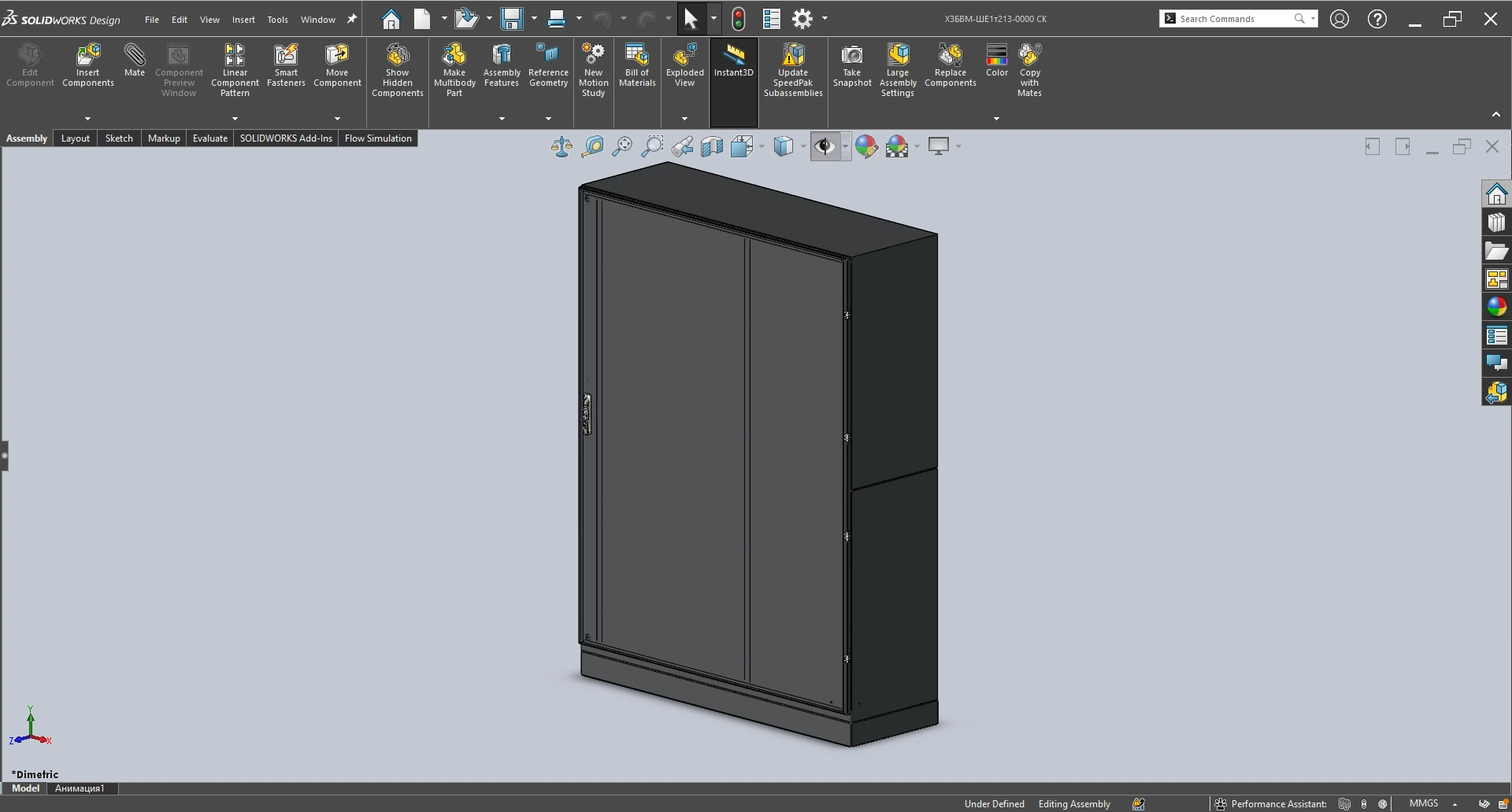
SolidWorks · real file, feature treeElectrical cabinet assembly with the feature tree open in SolidWorks
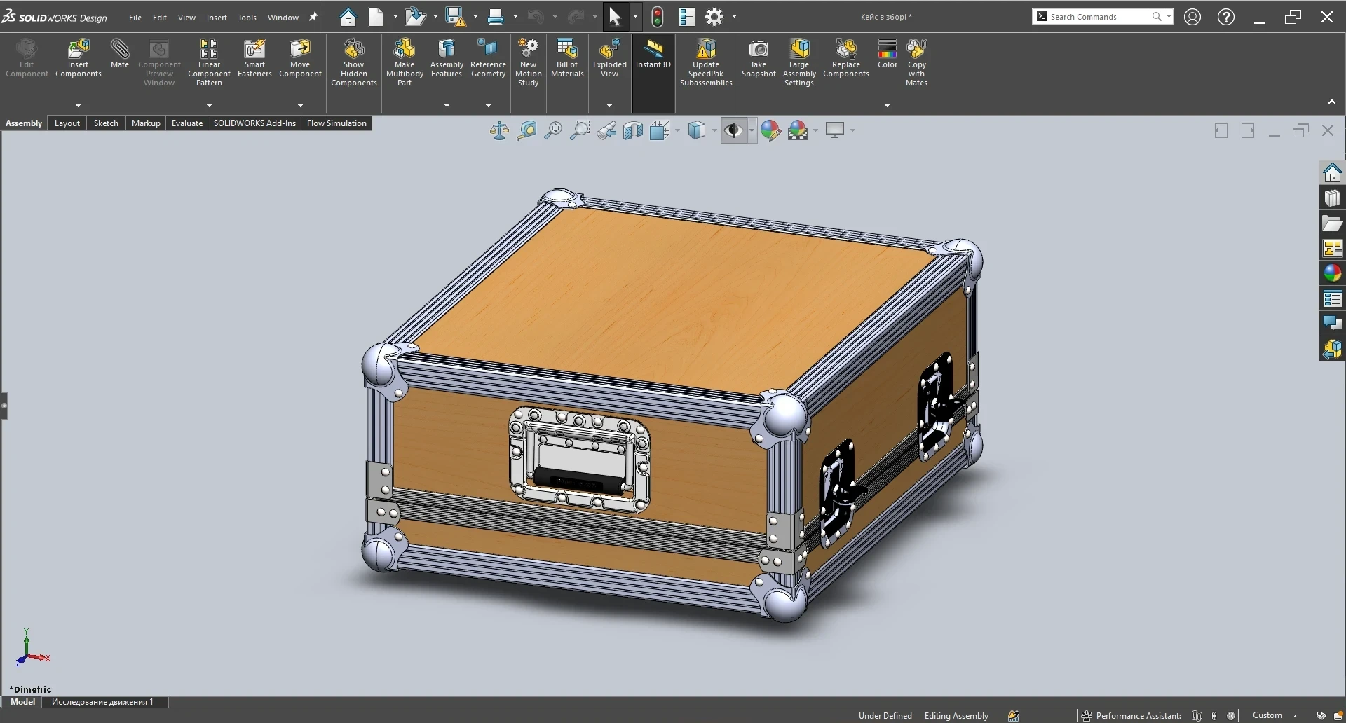
Assembly · mates and nesting levelsTransport case assembly built with mates in SolidWorks
Discipline 02 / LOAD ANALYSIS

Load analysis

Before the first part is cut, the structure is loaded in SolidWorks Simulation: where it bends, where stress concentrates, what safety factor is left. Cheaper to find in the model than in the field.

I apply the real load case — self weight, wind, the person hanging off the bar, snow on the canopy — not a round number chosen for comfort.

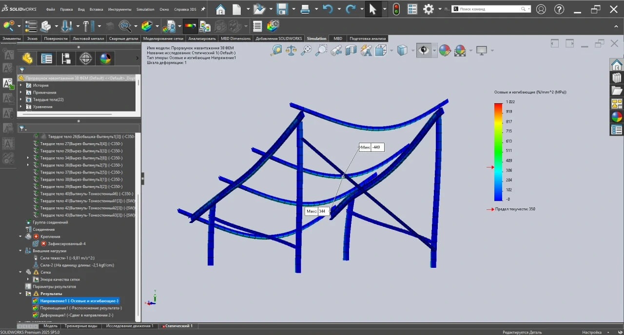
The result is a stress plot and a displacement plot with numbers you can act on: peak von Mises stress, deflection, and the safety factor against the material's yield strength.

Where the factor is too low I thicken the section or add a gusset. Where it is far too high I remove metal, because excess steel is money spent on nothing.

.PDFAnalysis report
with plots and numbers
PLOTStress and displacement
distribution
FoSSafety factor
against yield
REVRevised model
after optimisation
Discuss an analysis
Simulation · von Mises stress distributionVon Mises stress plot of a canopy frame in SolidWorks Simulation
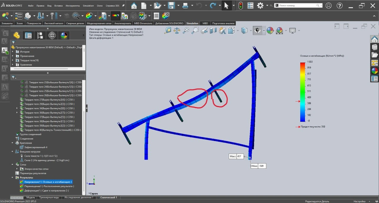
Node detail · stress concentrationClose-up of a welded node in a finite element analysis plot
Discipline 03 / DOCUMENTATION

Production drawings

The package the shop actually works from: assembly drawing, part drawings, bill of materials, and where required a product passport and an installation manual. Issued to ISO, or to DSTU and GOST for Ukrainian manufacturers.

Every sheet is dimensioned for the process that will make the part — bend lines for the press brake, weld symbols the welder reads without asking, tolerances only where a tolerance actually matters.

The bill of materials lists the structure, material grades and quantities, so procurement can order steel straight from it.

Drawings go out as PDF for printing plus AutoCAD-compatible DWG for anyone who needs to edit them.

.PDFPrint-ready
sheets
.DWGAutoCAD-compatible
editable
BOMBill of materials
with grades and quantities
MANUALPassport and
installation manual
See real drawing samples
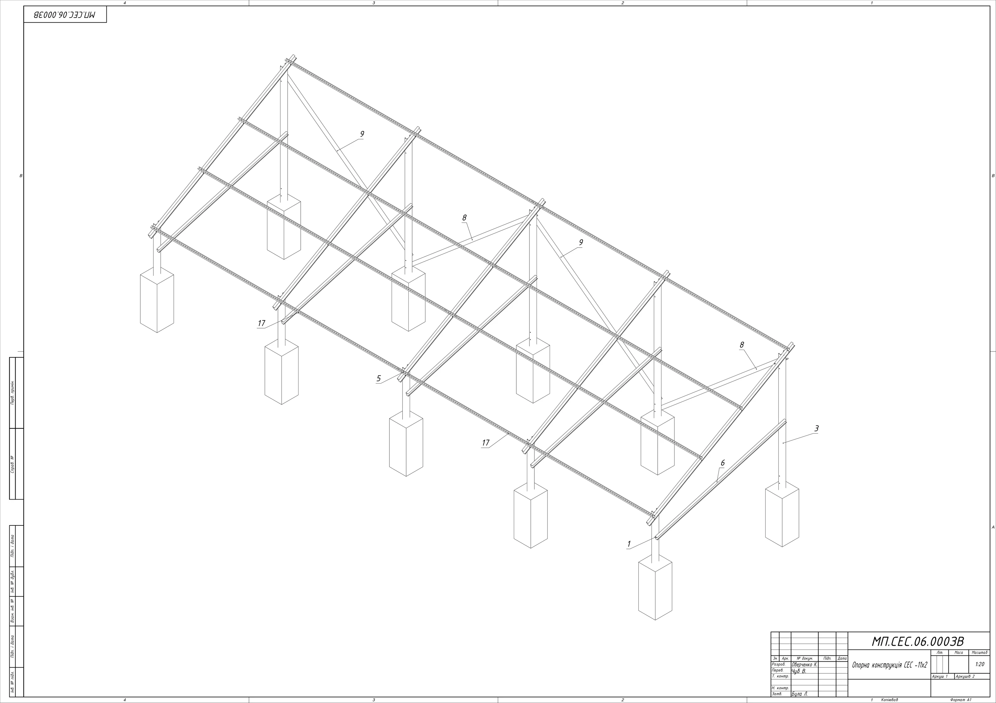
General arrangement · item numbersA1 general arrangement sheet of a solar PV support structure with item numbers
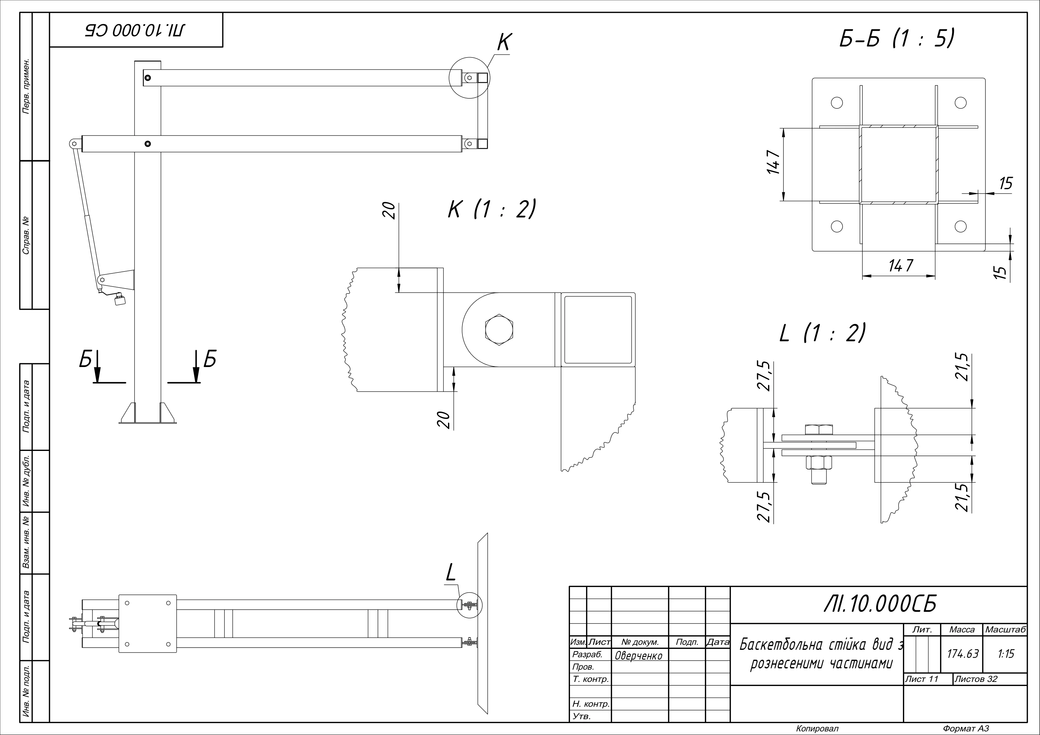
Part details · dimensions and weldsDetail drawings of parts with dimensions and weld symbols
Discipline 04 / SHEET METAL

Sheet metal and DXF

Sheet parts modelled as sheet metal from the start, so the flat pattern is correct — bend allowance calculated from the K-factor and the actual bend radius, not approximated afterwards.

The rule that saves most scrap: minimum bend radius against sheet thickness. A cut placed too close to a bend line tears; I move it before it reaches the shop.

Cut-outs, reliefs and hole positions are set so the part survives bending without distortion and still fits the assembly afterwards.

You receive DXF files that go to the laser without rework, plus drawings showing bend lines and the bend sequence.

.DXFFlat pattern
ready for the laser
K-FACTORCorrect bend
allowance
.STEP3D part
for reference
.PDFBend lines and
bend sequence
Send a part for a quote
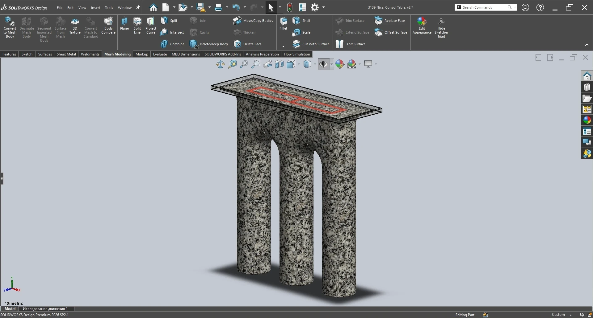
Sheet metal · parametric modelParametric sheet metal model of a console table in SolidWorks
WHO THIS IS FOR

Typical starting points

DWG-204
CLIENTS
4 CASES

Manufacturers outsource design to me for the same reason they outsource anything: a full-time engineer is a fixed cost, and design work arrives in bursts. You get the capacity when a project needs it and nothing between projects.

Work is fully remote and the deliverables are files, so the time zone matters more than the distance. Correspondence in English, drawings to ISO, NDA signed on your template before details are discussed.

NEXT STEP

Send a sketch — get a quote in 24 hours

DWG-205
START
NOW

No written specification needed. A photo, a hand sketch or a sample is enough to start — the rest we work out together.

Send your brief