X:000 Y:000
+38 (098) 043-34-20 Telegram
PORTFOLIO · DWG-301 · CASE 01 · STEEL FRAME

CARPORT parking canopy: from renders to a truss the shop could actually weld

A modular steel car canopy for snow up to 180 kg/m² and wind zone IV. It started as a 3D model and renders for a presentation and ended as a full set of working drawings, because without them the shop could not weld the truss.

9230mm
length
180kg/m²
snow
IVwind
zone
19drawing
sheets
THE BRIEF

What had to be delivered

DWG-311
BRIEF
PRIVATE DEVELOPER · 2025

The client was a private developer. The first request was simple: a 3D model of a parking canopy and renders for a presentation. I delivered the model and 18 renders.

A month later a second message arrived: «The shop says they need drawings, they couldn't figure out how to weld the truss.» A presentation model shows what the product looks like, but it doesn't tell a welder what lengths to cut, at what angle, and where to weld the bolt lug. That is where the second part of the job came from: working drawings.
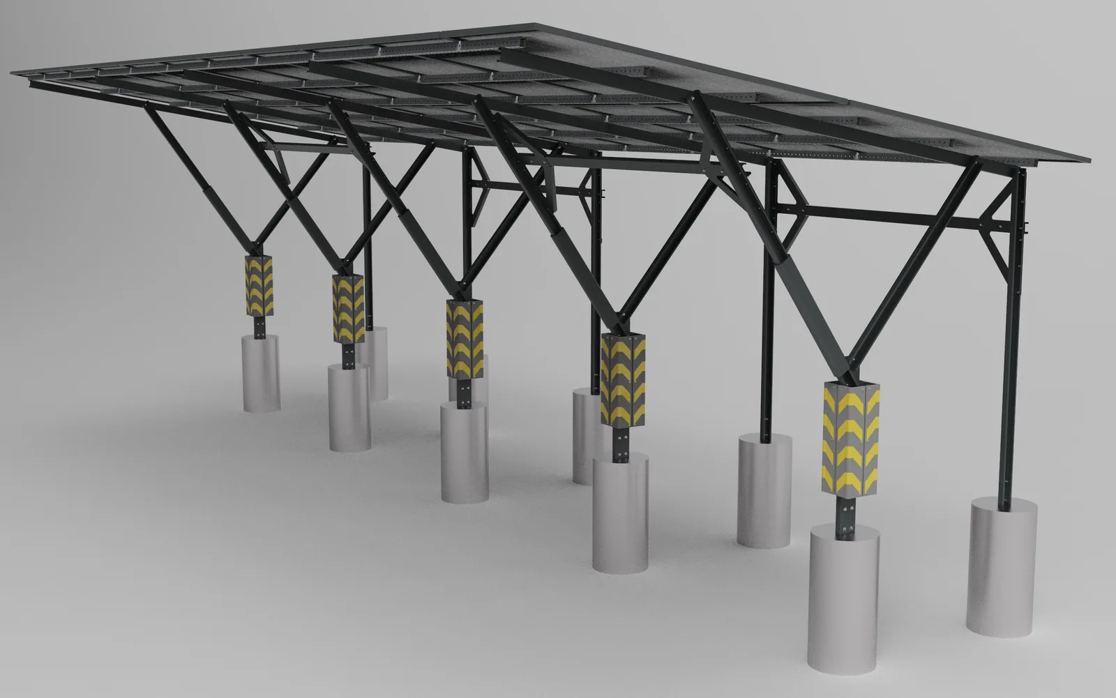
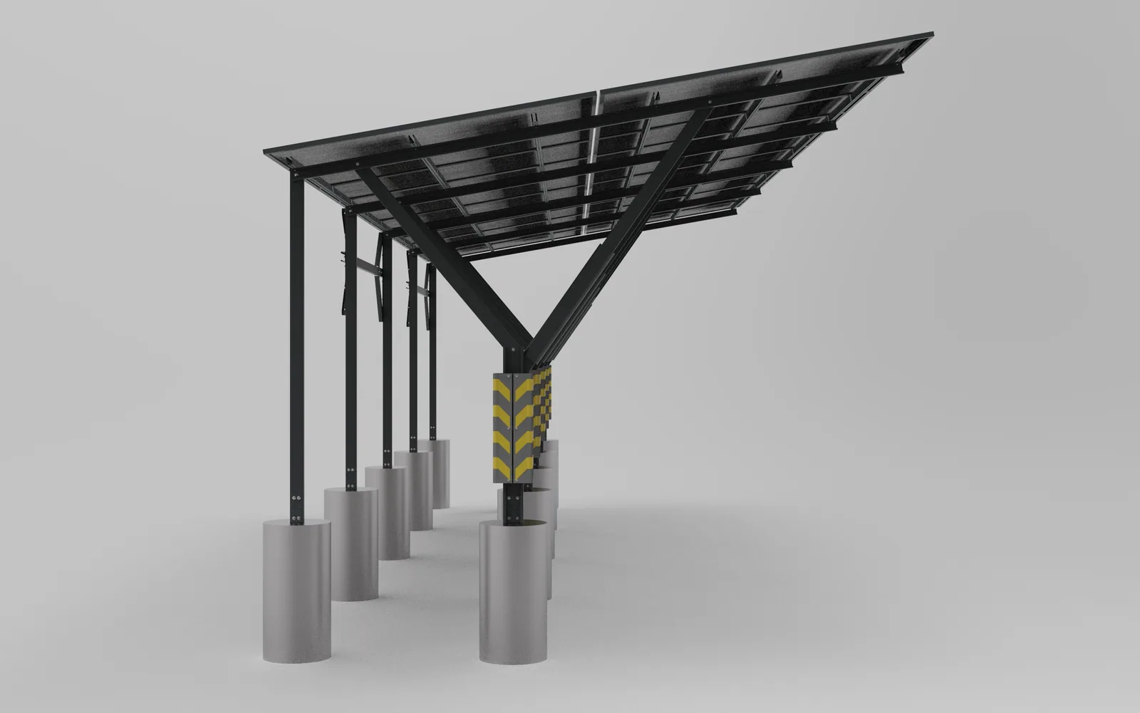
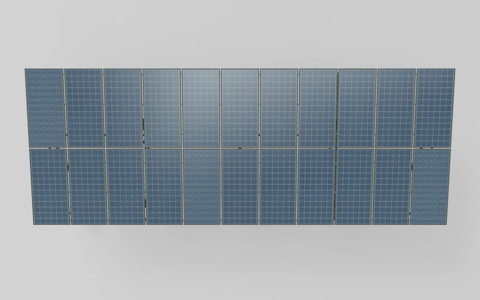
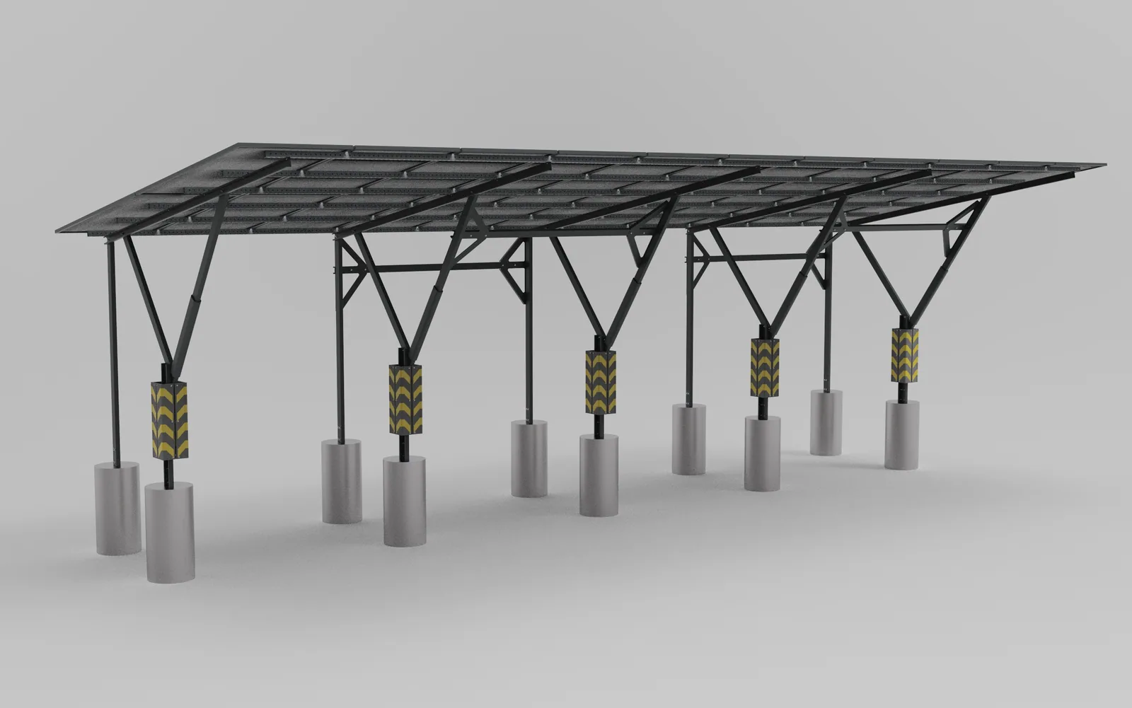
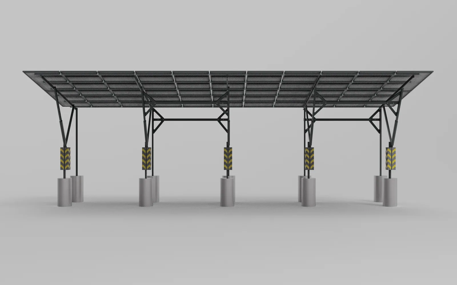
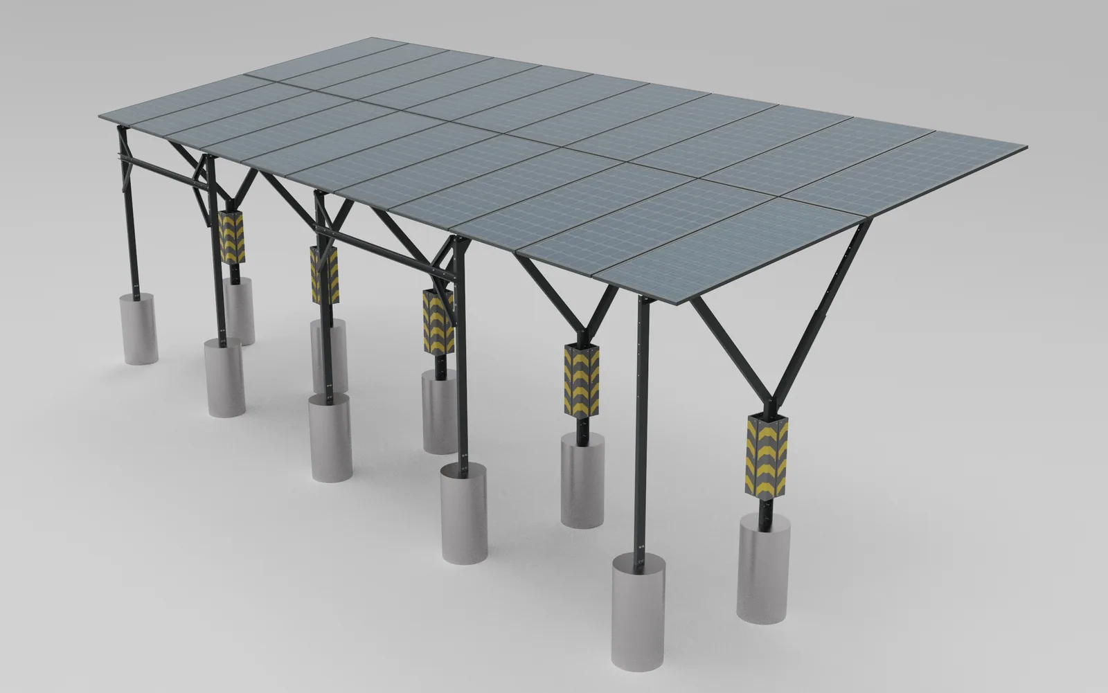
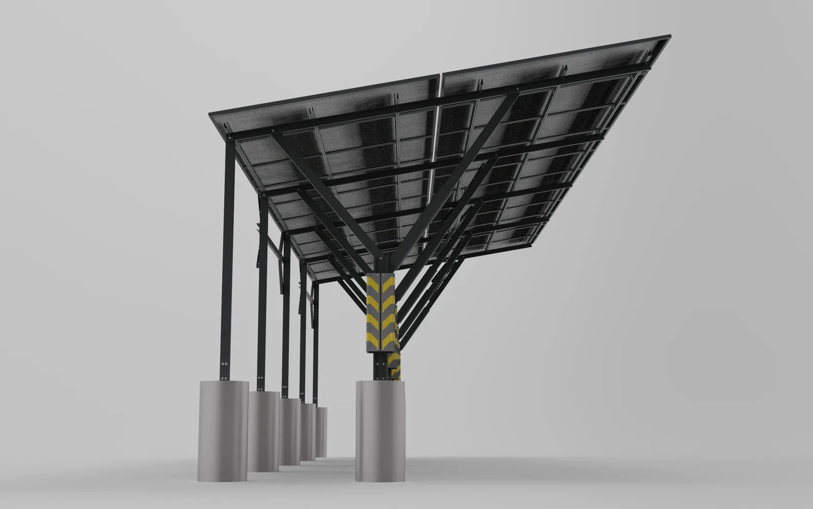
CARPORT · KeyShot render CARPORT parking canopy — steel car canopy frame, KeyShot 3D render
ENGINEERING CONSTRAINT

What made it non-trivial

DWG-312
CONSTRAINTS
4 ITEMS

The canopy is one of the two largest structures in the portfolio, and one where the profile section is set by weather, not by self-weight.

Snow up to 180 kg/m². On a 9.2 × 3.2 m roof that is more than five tonnes of distributed load, which the trusses must carry to the posts without the purlins sagging.

Wind zone IV. The canopy is open, so wind acts on the roof both as pressure and as uplift. It was the wind load, not snow, that set the profile section.

Thin-walled tube. The trusses are made of 60×60×2, 60×40×1.8 and 40×25 mm hollow sections: light and cheap, but with a 1.8–2 mm wall every joint has to be designed, not «welded however it fits».

A shop without an engineer. The drawings had to answer every question a welder might have without a phone call: lengths, cut angles, lug positions.

SOLUTION

How I solved it

DWG-313
METHOD
5 STEPS

The frame is split into assemblies that are welded in the shop and bolted together on site. Welding stays where there is a table and a jig; installation only needs a spanner.

01

Repetition: 7 identical central trusses, two side trusses and purlins on a single 1125 mm pitch. Fewer unique parts means fewer chances to mix them up

02

Trusses are welded from hollow sections using part drawings that give each brace its length and both cut angles

03

Purlins attach to the trusses through welded lugs with M10 DIN933 bolts: 32 cross members, 8 end ones and 24 with through holes

04

Post bases and three consoles of different lengths are separate items with their own sheets, so each part is cut from its own drawing

05

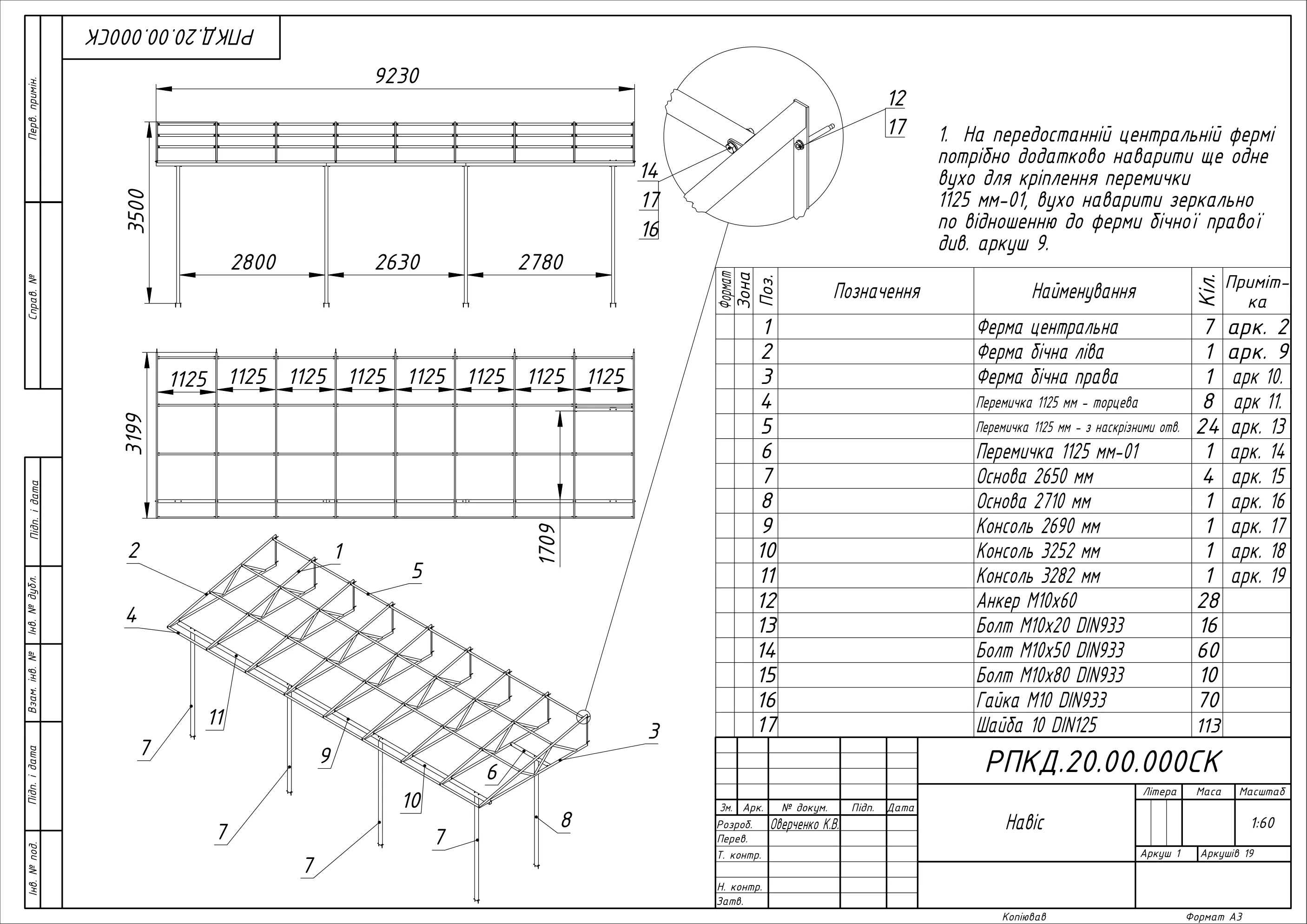
The general arrangement carries a note for the shop: weld one extra lug on the second-to-last central truss, mirrored to the right side truss. Otherwise the welder would find out on site

РПКД.20.00.000СК · general arrangement · A3 · 1:60 General arrangement sheet of the canopy: overall 9230 × 3199 × 3500 mm, 1125 mm purlin pitch, 17-item bill of materials
STRUCTURE

Structure and materials

DWG-314
BOM
4
7+2trusses
central and side
32cross members
1125 mm each
M10bolted joints
DIN933 / DIN125
28anchors
M10×60

Hollow sections 60×60×2, 60×40×1.8 and 40×25 mm, 3 mm hot-rolled plate for lugs and plates, 140×140×4 mm tube. Standard fasteners (DIN933, DIN125) available at any hardware supplier.

Overall size per drawing: 9230 mm long, 3199 mm wide, 3500 mm high. Posts stand at 2800, 2630 and 2780 mm spacing; the roof is divided by purlins into eight 1125 mm bays.

DOCUMENTATION

What went to the shop

DWG-315
OUTPUT
3 FILES

The set: general arrangement with a 17-item bill of materials, drawings of the central and side trusses, cross members, bases and consoles — with lengths, cut angles and hole positions. General arrangement at 1:60, parts at 1:20 and 1:5.

GALLERY

Renders for the presentation

DWG-316
RENDERS
6 SHOTS
RESULT

Result and lesson

DWG-317
RESULT

The client got documentation the shop can work from without an engineer standing next to it: tube is cut to the lengths and angles on the drawing, the truss is assembled from its sheet, and joints use standard bolts.

Producing the full drawing set after the presentation model cost the client roughly +40% in time and budget. Agreeing on what goes to production at the start would have saved a week of back-and-forth. Since then, the first thing I ask on every project is what exactly the shop needs.

NEXT STEP

Similar task?

DWG-318
LINKS
4

Send a sketch or a photo — within 24 hours I'll tell you how long it takes and what I need from you.

Discuss your project Message on Telegram